AUTOMATIC TRANSAXLE REMOVAL/INSTALLATION [LF]
1. Remove the battery duct and battery cover. (See BATTERY REMOVAL/INSTALLATION [LF].)
2. Disconnect the negative battery cable.
3. Remove the following parts.
- (1) Battery, battery tray and battery box. (See BATTERY REMOVAL/INSTALLATION [LF].)
- (2) Air cleaner component. (See INTAKE-AIR SYSTEM REMOVAL/INSTALLATION [LF].)
- (3) Exhaust manifold insulator.
- (4) Front tires and splash shield.
- (5) Under cover.
4. Drain the ATF. (See AUTOMATIC TRANSAXLE FLUID (ATF) REPLACEMENT.)
- • Improperly jacking a transaxle is dangerous. It can slip off the jack and may cause serious injury.
- • To prevent the torque converter and transaxle from separating, remove the transaxle without tilting it toward the torque converter.
5. Remove in the order indicated in the table.
6. Install in the reverse order of removal.
7. Add ATF to the specified level. (See AUTOMATIC TRANSAXLE FLUID (ATF) REPLACEMENT.)
8. Perform the following test. (See MECHANICAL SYSTEM TEST.)(See ROAD TEST.)
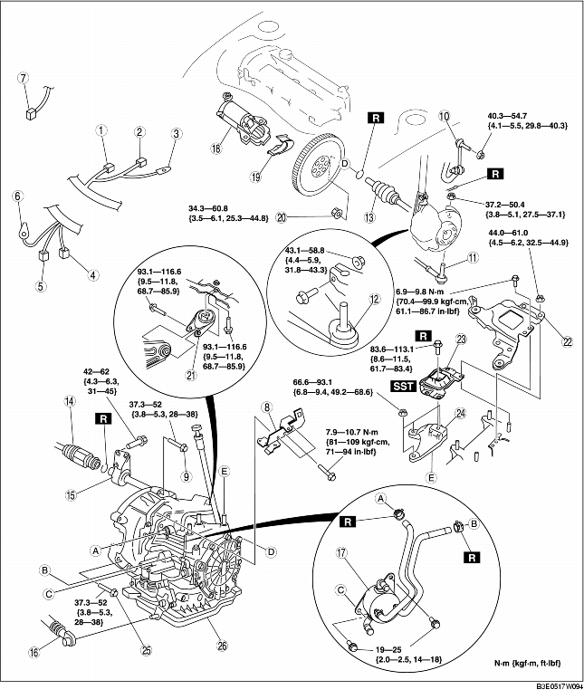
|
1
|
Input/turbine speed sensor connector
|
|
2
|
VSS connector
|
|
3
|
GND wiring harness
|
|
4
|
Transaxle connector
|
|
5
|
TR switch connector
|
|
6
|
GND wiring harness
|
|
7
|
Oil pressure switch connector (for oil filter)
|
|
8
|
Harness bracket
|
|
9
|
Transaxle mounting bolt (upper side)
|
|
10
|
Stabilizer control link
|
|
11
|
Tie-rod end ball joint
|
|
12
|
Lower arm ball joint
|
|
13
|
Drive shaft
|
|
14
|
Drive shaft
|
|
15
|
Joint shaft
|
|
16
|
Selector cable
|
|
17
|
Oil cooler
|
|
18
|
Starter
|
|
19
|
End plate cover
|
|
20
|
Torque converter installation nuts
|
|
21
|
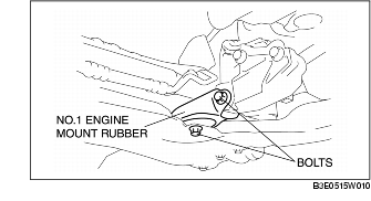
No.1 engine mount rubber
|
|
22
|
Battery tray bracket
|
|
23
|
No.4 engine mount rubber
|
|
24
|
No.4 engine mount bracket
|
|
25
|
Transaxle mounting bolt (lower side)
|
|
26
|
Transaxle
(See Transaxle Removal Note.)
(See Transaxle Installation Note.)
|
Torque Converter Nuts Removal Note
1. Hold the crankshaft pulley to prevent the drive plate from rotating.
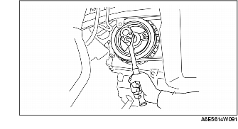
2. Remove the torque converter nuts from the starter installation hole.

No.4 Engine Mount Removal Note
1. To prevent crushing the front fender panel, insert a wood slab of appropriate size between the front fender panel and upper apron reinforcement.
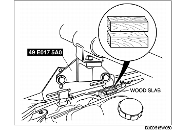
4 door: approx. 35 mm {1.4 in}
5 door: approx. 60 mm {2.4 in}
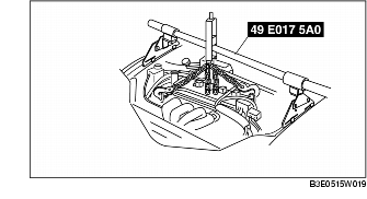
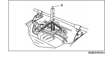
2. Support the engine using the SST.
3. Remove the battery tray bracket, No.4 engine mount rubber and bracket.
Transaxle Removal Note
1. Loosen the part marked A and lean the engine toward the transaxle.
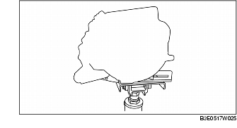
2. Support the transaxle on a jack.
3. Remove the transaxle mounting bolts.
4. Remove the transaxle.
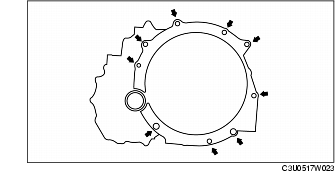
Transaxle Installation Note
1. Set the transaxle on a jack and lift it.
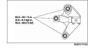
2. Install the transaxle mounting bolts.
Tightening torque
No.1 Engine Mount and No.4 Engine Mount Installation Note
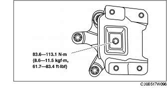
1. Install the No.4 engine mount bracket on the transaxle case and tighten nuts.
2. Install the No.1 engine mount rubber to the crossmember and temporarily tighten bolts.
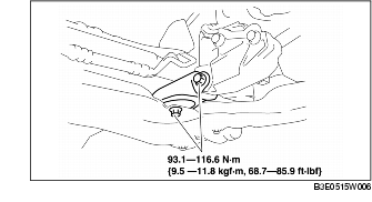
3. Place the No.4 engine mount rubber with the body stud bolts passing through the holes and tighten the new bolt as shown in the figure.
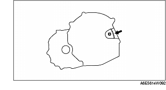
4. Place the battery tray bracket on the No.4 engine mount rubber with body stud bolts passing through the holes and tighten bolts and nuts in the order as shown in the figure.

5. Fully tighten the bolts
6. Remove the SSTs.
Torque Converter Nuts Installation Note
1. Hold the crankshaft pulley to prevent the drive plate from rotating.

- • Loosely and equally tighten the torque converter nuts, then further tighten them to the specified tightening torque.
2. Tighten the torque converter mounting nuts.
Tightening torque