BATTERY REMOVAL/INSTALLATION [LF]
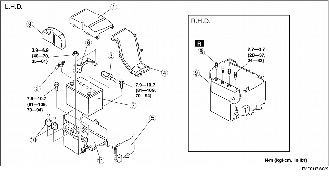
1. Remove in the order indicated in the table.
2. Install in the reverse order of removal.
|
1
|
Battery cover
|
|
2
|
Negative battery cable
|
|
3
|
Positive battery cable
|
|
4
|
Battery duct
|
|
5
|
Battery box
|
|
6
|
Battery clamp
|
|
7
|
Battery
|
|
8
|
Set bolt
(See Set Bolt Removal Note.)
|
|
9
|
PCM cover
|
|
10
|
Connectors
|
|
11
|
Battery tray and PCM component
|
Set Bolt Removal Note
1. Drill the set bolts using a drill bit with a diameter larger than the shanks until the heads are removed.
2. Clean all foreign material from the PCM connectors.
PCM Cover Installation Note (L.H.D.)
1. Install with the PCM cover hooks B aligned with the PCM box holes.
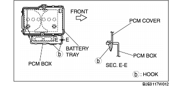
2. Install the PCM cover to the PCM box hook.
PCM Cover Installation Note (R.H.D.)
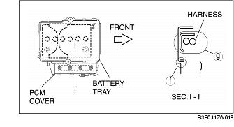
1. Insert the tab of the PCM cover to the hole.
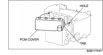
2. Rotate until area F is parallel. The harness and the PCM cover should be located at area G.
Set Bolt Installation Note
1. Install new set bolts and temporarily tighten them first, then tighten them until the necks of the bolts break off.
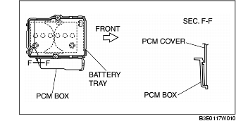
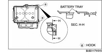
Battery Box Installation Note
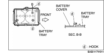
1. Assemble with battery box hooks E aligned with the battery tray holes at two points.
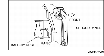
Battery Duct Installation Note
1. Match the mark of the shroud panel and notch in the battery duct, and install the battery duct to the shroud panel.
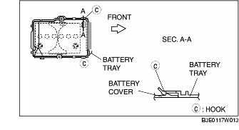
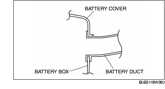
Battery Cover Installation Note
1. Install the battery duct between the battery cover and the battery box.
2. Install with battery cover hooks A aligned with the battery tray holes at two points.
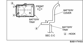
3. Install with battery cover hooks D aligned with the battery tray flange at two points.
4. Set the battery cover to battery tray hooks C at two points.