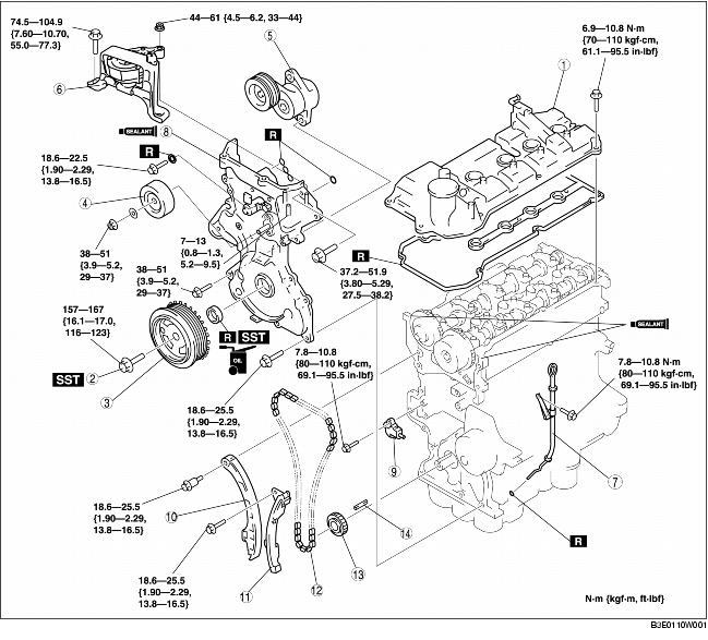
TIMING CHAIN REMOVAL/INSTALLATION [ZJ, Z6]
- • Fuel vapor is hazardous. It can very easily ignite, causing serious injury and damage. Always keep sparks and flames away from fuel.
- • Fuel line spills and leakage are dangerous. Fuel can ignite and cause serious injuries or death and damage. Fuel can also irritate skin and eyes. To prevent this, always complete the "Fuel Line Safety Procedure". (See AFTER SERVICE PRECAUTION [ZJ, Z6, LF].)
1. Remove the battery cover.
2. Disconnect the negative battery cable.
3. Drain the engine coolant. (See ENGINE COOLANT REPLACEMENT [ZJ, Z6, LF].)
4. Remove the front wheel and tire (RH). (See GENERAL PROCEDURES (SUSPENSION).)
5. Remove the under cover and splash shield (RH).
6. Remove the air cleaner component. (European (L.H.D.) specs.) (See INTAKE-AIR SYSTEM REMOVAL/INSTALLATION [ZJ, Z6].)
7. Remove the air cleaner case and position the air cleaner cover out of the way with the PCM connector still connected. (U.K. specs.) (See INTAKE-AIR SYSTEM REMOVAL/INSTALLATION [ZJ, Z6].)
8. Remove the following parts:
- (1) Ignition coils (See IGNITION COIL REMOVAL/INSTALLATION [ZJ, Z6].)
- (2) Drive belt (See DRIVE BELT REPLACEMENT [ZJ, Z6].)
- (3) P/S oil pump with the oil hose and oil pipe still connected (See POWER STEERING OIL PUMP (ZJ, Z6) REMOVAL/INSTALLATION.)
- (4) Coolant and P/S reserve tank with the hoses and pipes still connected
- (5) Generator (See GENERATOR REMOVAL/INSTALLATION [ZJ, Z6].)
- (6) Water pump (See WATER PUMP REMOVAL/INSTALLATION [ZJ, Z6].)
- (7) Accelerator cable bracket (body side)
- (8) Earth (No.3 engine mount)
9. Disconnect the following parts:
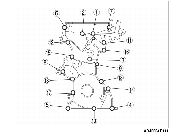
10. Remove in the order indicated in the table.
11. Install in the reverse order of removal.
12. Start the engine.
13. Inspect the following and adjust them if necessary.
- (1) Amount of engine oil (See ENGINE OIL LEVEL INSPECTION [ZJ, Z6, MZ-CD 1.6 (Y6)].)
- (2) Pulley and belt for runout and contact
- (3) Ignition timing and idle speed. Verify the amount of CO and HC. (See ENGINE TUNE-UP [ZJ, Z6].)
14. Perform a road test and verify that there is no abnormal vibration or noise.
|
1
|
Cylinder head cover
|
|
2
|
Crankshaft pulley installation bolt
|
|
3
|
Crankshaft pulley
|
|
4
|
Idler pulley
|
|
5
|
Drive belt auto tensioner
|
|
6
|
No.3 engine mount
|
|
7
|
Oil level gauge pipe
|
|
8
|
Engine front cover
|
|
9
|
Chain tensioner (See Chain Tensioner Removal Note.)
|
|
10
|
Chain tensioner arm
|
|
11
|
Chain guide
|
|
12
|
Timing chain (See Timing Chain Removal Note.) (See Timing Chain Installation Note.)
|
|
13
|
Crankshaft sprocket
|
|
14
|
Key
|
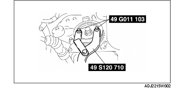
Crankshaft Pulley Installation Bolt Removal Note
1. Fix the crankshaft pulley using the SSTs.
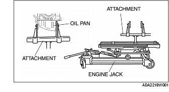
No.3 Engine Mount Removal Note
1. Secure the engine using an engine jack and attachment.
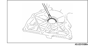
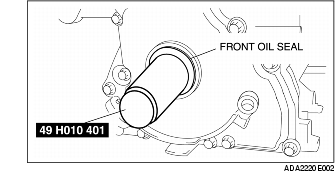
Engine Front Cover Removal Note
1. Remove the front oil seal using a flathead screwdriver.
Chain Tensioner Removal Note
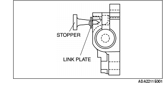
1. Push down the link plate of the timing chain tensioner using a thin flathead screwdriver (precision screwdriver), and release the plunger lock.
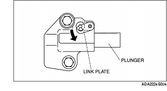
2. Push back the plunger slowly in the direction shown in the figure with the link plate still pushed down.
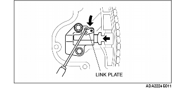
3. Release the link plate with the plunger still pressed down.
4. Release the pressure slightly from the plunger, and move the plunger back and forth 2-3 mm {0.08-0.11 in).
5. Insert an approx. 1.5 mm {0.06 in) thick wire or paper clip where the link plate hole and the tensioner body hole overlap to fix the link plate and lock the plunger.

Timing Chain Removal Note
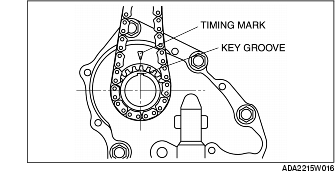
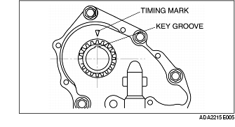
1. Rotate the crankshaft clockwise and align the key groove of the crankshaft sprocket with the timing mark, and then position the No.1 cylinder to TDC.
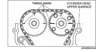
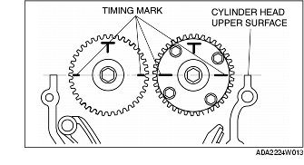
2. Align the timing marks on the camshaft sprockets so that they form a straight line in alignment with the upper horizontal surface of the cylinder head.
3. Remove the timing chain.
Timing Chain Installation Note
1. Align the key groove of the crank sprocket to the timing mark, and then position the No.1 cylinder to TDC.
2. Align the timing marks on the camshaft sprockets so that they form a straight line in alignment with the upper horizontal surface of the cylinder head.
3. Install the timing chain.
4. After installing the chain adjuster, remove the wire or the paper clip installed to the chain tensioner, and apply tension to the timing chain. (Remove the installed stopper when installing the new chain tensioner.)
5. Verify that there is no slack on the timing chain, and then verify that each sprocket is positioned in the proper place again.
6. Rotate the crankshaft clockwise twice, and then inspect the valve timing.
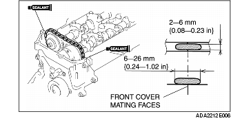
Engine Front Cover Installation Note
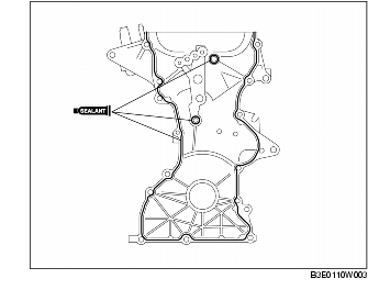
1. Apply the silicon sealant to the engine front cover as shown in the figure.
2. Tighten the engine front cover installation bolts in the order shown in the figure.
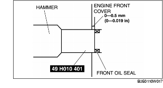
3. Apply clean engine oil to the new front oil seal.
4. Insert the front oil seal into the engine front cover by hand.
5. Tap in the front oil seal using the SST and a hammer.
Compression amount
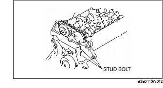
No.3 Engine Mount Installation Note
1. Tighten the No.3 engine mount installation stud bolts.
Tightening torque
2. Install the No.3 engine mount and temporarily tighten the installation bolts and nuts.
3. Tighten the installation bolts in the order shown in the figure.
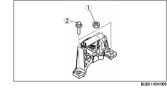
Tightening torque
- 1 (nuts) : 44-61 N·m {4.5-6.2 kgf·m, 33-44 ft·lbf}
- 2 (bolts) : 74.5-104.9 N·m {7.60-10.70 kgf·m, 55.0-77.3 ft·lbf}
Crankshaft Pulley Installation Bolt Installation Note
1. Fix the crankshaft pulley using the SSTs.

2. Tighten the crankshaft pulley installation bolt.
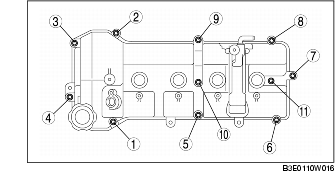
Tightening torqueCylinder Head Cover Installation Note
1. Apply silicon sealant as shown in the figure.
Thickness Length
2. Tighten the cylinder head cover installation bolts in the order shown in the figure.
Tightening torque