INPUT/OUTPUT CHECK MODE OPERATION
B3E092255430T06
Operation procedure
• Refer to Mazda3 Workshop Manual.
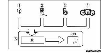
Input circuit check
• When the parts listed in the chart are operated and signal is output to the instrument cluster, the built-in microcomputer determines the operability of the input circuit based on that signal.
|
Check code
|
Parts sending input signal
|
|---|---|
|
08
|
TNS relay
|
|
22
|
Fuel gauge sender unit
|
|
31
|
Key reminder switch (built into the ignition switch)
|
|
55
|
Dimmer switch (built into the instrument cluster)
|
|
1
|
TNS relay
|
|
2
|
Fuel gauge sender unit
|
|
3
|
Key reminder switch (ignition switch)
|
|
4
|
Dimmer switch
|
|
5
|
Instrument cluster
|
|
6
|
Microcomputer
|
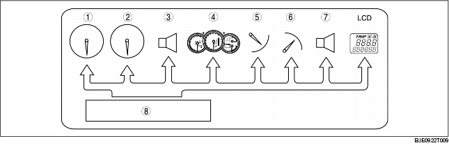
Individual circuit check
• By operating the parts listed in the chart, the built-in microcomputer determines the operability of the individual parts.
|
1
|
Speedometer
|
|
2
|
Tachometer
|
|
3
|
Buzzer
|
|
4
|
Warning and indicator light
|
|
5
|
Fuel gauge
|
|
6
|
Water temperature gauge
|
|
7
|
Indicator buzzer
|
|
8
|
Microcomputer
|
PID/Data Monitor and Record
• The PID/data monitoring items for the instrument cluster is as shown in following the table:
Monitor item table
-: Not applicable