FUEL INJECTION CONTROL OPERATION [ZJ, Z6]
B3E014000140T24
Injection Timing
• There is synchronized fuel injection, which performs fuel injection by the setting of the crankshaft position, and non-synchronized fuel injection which performs fuel injection when the condition for fuel injection is met regardless of the crankshaft position.
Synchronized fuel injection
- • The crankshaft rotation is synchronized by each intake and exhaust stroke of the cylinders, and fuel injection is performed by the fuel injection timing and the injection amount corresponding to the input signals of the following sensors.
- - ECT sensor
- - IAT sensor
- - CKP sensor
- - MAF sensor
Non-synchronized fuel injection
- • The crankshaft rotation is not synchronized and fuel injection is performed by the injection timing and injection amount as triggered by the input signals of the following sensors.
- - ECT sensor
- - IAT sensor
- - TP sensor
- - MAF sensor
Relation between synchronized and non-synchronized fuel injection
- • If synchronized and non-synchronized fuel injection happen to occur together, fuel is injected by adding the fuel injection timing of both.
Injection time
• The PCM calculates the fuel injection amount according to the engine operation conditions as the fuel injection time and energizes the fuel injectors.
Fuel injector energization time and operation conditions
-
• The fuel injectors cause an operation delay with the start of energization from the PCM. The PCM calculates the fuel injection time by adding the non-injection time (ineffective injection time) to the actual injection time (effective injection time), and energizes the fuel injectors for this time.
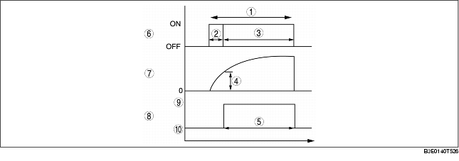
Fuel injection time = effective injection time + ineffective injection time
Ineffective injection time- - The fuel injectors cause a delay in operation due to a delay in the build-up of operation current from coil inductance with the start of energization, and by the mass of the needle valve and plunger, and spring resistance. This delay is the ineffective injection time.
- - The non-injection time is affected by the change in battery voltage. Accordingly, the PCM sets the non-injection time according to the battery voltage.
- - The fuel injector opening valve time which is the actual fuel injection time is called the effective injection amount.
Determination of effective injection time
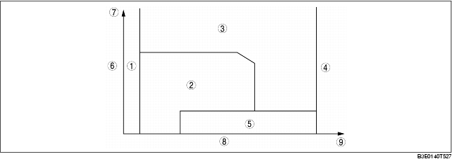
• The PCM divides the engine operation conditions into control zones according to engine speed and engine load and determines the effective injection time at each control zone to perform optimum air/fuel ratio control in all engine driving ranges.
|
1
|
Start Zone
|
|
2
|
Feedback zone
|
|
3
|
High Load Volume Increase Zone
|
|
4
|
Excessive Speed Fuel Cut Zone
|
|
5
|
Deceleration Fuel Cut Zone
|
|
6
|
Intake air amount
|
|
7
|
Large
|
|
8
|
Engine speed
|
|
9
|
High
|
Start zone
Purpose Control condition Determination of fuel injection timeFeedback Zone
Purpose Control condition Determination of fuel injection time- • During normal driving, the injection time is determined by the front and rear HO2S and sets to the theoretical air/fuel ratio.
High load volume increase zone
Purpose Control condition- • Either the engine speed, charging efficiency or throttle valve opening angle is a fixed value or more.
- • Corrections are added to the basic injection amount and the high load coefficient is calculated according to the engine speed, mass intake airflow amount and the throttle valve opening angle.
Excessive speed fuel cut zone
Purpose Control conditions- • Engine speed is approx. 6,500 rpm or more
- • When the following conditions continue for 2 min or more:
- - Vehicle is stopped.
- - Engine speed is 5,000 rpm or more.
- - Engine coolant temperature is 110°C {230°F} or more.
Deceleration Fuel Cut Zone
Purpose Control condition- • When the engine conditions are as follows (5 s or more after shifting the selector lever to other than P, N, or R, and 10 s or more after engine start):
- - Fully-closed throttle valve during deceleration (charging at fixed value or more)
- - During driving under high load at engine speed of 1,000 rpm or more (mass airflow sensor normal)
Calculation method table for fuel injection time
(*: Fuel injection time base, x: Correction for fuel injection time)
Fuel Cut
• Includes fuel cut under the following conditions except fuel cut at excessive engine speed according to engine operation and deceleration fuel cut.
Sensor damage fuel cut
Purpose- • To prevent engine damage from abnormal ignition due to a malfunction input of a cylinder identification or the engine speed signal.
Dechoke Control
Purpose Execution conditionFuel Cut During Immobilizer System Activation
Purpose Execution conditions- • When an engine stop request signal is received from the immobilizer system, the PCM force-stops the fuel injectors. Therefore the engine stops.